


Ask any substation maintenance engineer what single intervention has prevented the most Indoor VCB failures over their career, and the answer is almost never a major overhaul or a component replacement. It is lubrication — applied correctly, to the right components, with the right material, at the right interval. Yet across medium voltage substations worldwide, operating mechanism lubrication remains one of the most inconsistently executed maintenance tasks in the entire MV reliability program. Teams either over-lubricate with the wrong grease, creating contamination that accelerates wear, or under-lubricate through neglect, allowing metal-to-metal contact that progressively destroys precision-machined surfaces. A correctly executed lubrication program for an Indoor VCB operating mechanism is not a routine housekeeping task — it is a primary reliability intervention that directly determines whether the breaker trips in 25 milliseconds or fails to trip at all. This guide provides the complete technical framework: which components require lubrication, which materials to use, how to execute the procedure, and how to build a lifecycle maintenance schedule that sustains substation reliability across a 30-year service horizon.
Table of Contents
- Which Operating Mechanism Components Require Lubrication in an Indoor VCB?
- What Lubricant Specifications Apply to Medium Voltage VCB Mechanisms?
- How to Execute a Complete Operating Mechanism Lubrication Procedure?
- How to Build a Lifecycle Lubrication Schedule for Substation VCB Reliability?
Which Operating Mechanism Components Require Lubrication in an Indoor VCB?

The operating mechanism of an Indoor VCB is a precision kinematic system — a carefully engineered sequence of levers, cams, latches, and linkages that must convert stored energy (spring or magnetic) into a controlled contact travel motion within a defined time window. Every friction interface in that system is a potential failure point, and every failure point has a lubrication requirement. Understanding which components need lubrication — and why — is the foundation of an effective maintenance program. Applying grease randomly to visible metal surfaces is not lubrication maintenance; it is contamination.
Primary Mechanism Components and Their Lubrication Requirements
1. Main Operating Shaft and Bearings
The main shaft transmits rotational force from the energy storage element (spring or magnetic actuator) to the contact drive linkage. It runs in either plain bronze bushings or sealed ball bearings depending on the VCB design generation.
- Plain bronze bushings: require periodic grease replenishment — the bushing material is porous and retains lubricant, but this reservoir depletes over 3–5 years of operation1
- Sealed ball bearings: factory-lubricated for life in modern designs — do not require field lubrication, but must be inspected for seal integrity
2. Latch and Trip Mechanism
The latch assembly is the most precision-critical lubrication point in the entire mechanism. It consists of a hardened steel latch roller engaging a latch surface, held by a trip latch spring. The engagement geometry is typically designed with a latch engagement depth of 0.3 mm – 0.8 mm — a tolerance that makes this interface extremely sensitive to lubricant film thickness.
- Too little lubricant: latch roller friction increases, requiring higher trip coil force to release — creates slow trip times or no-trip failures
- Too much lubricant: excess grease migrates onto the latch engagement surface, reducing effective engagement depth and causing nuisance tripping under vibration
3. Closing Cam and Roller
The closing cam converts rotational shaft motion into linear contact drive motion. The cam-roller interface operates under high contact stress during the closing stroke and requires a lubricant with sufficient extreme pressure (EP) additives to prevent surface fatigue.2
4. Linkage Pins and Clevis Joints
Every pin joint in the operating linkage is a sliding friction interface. A typical spring-operated Indoor VCB mechanism contains 8–14 pin joints depending on design complexity. Each pin operates in a bronze or polymer bushing and requires a thin, consistent grease film.
5. Racking Lead-Screw and Guide Rails
As covered in previous technical analysis, the racking mechanism requires specific synthetic grease on both the lead-screw thread flanks and the guide rail contact surfaces — separate from the operating mechanism lubrication.
6. Spring Charging Mechanism (Spring-Type VCBs Only)
The motor-driven spring charging assembly includes a worm gear, ratchet mechanism, and spring guide tube — all requiring lubrication independent of the main operating mechanism.
Component Lubrication Summary
| Component | Lubrication Type | Interval | Critical Parameter |
|---|---|---|---|
| Main shaft plain bushings | Synthetic grease (NLGI 1-2) | 3 years | Film continuity |
| Latch roller and surface | Thin dry-film lubricant | 2 years | Film thickness control |
| Closing cam and roller | EP synthetic grease (NLGI 2) | 3 years | EP additive rating |
| Linkage pins and clevis joints | Synthetic grease (NLGI 1) | 3 years | Full pin coverage |
| Racking lead-screw | PTFE or lithium-complex grease | 1–2 years | Thread flank coverage |
| Spring charging worm gear | Synthetic gear oil or NLGI 2 grease | 3 years | Viscosity grade match |
| Sealed ball bearings | No field lubrication | Inspect seals only | Seal integrity |
What Lubricant Specifications Apply to Medium Voltage VCB Mechanisms?

Lubricant selection for VCB operating mechanisms is governed by three engineering constraints that eliminate most general-purpose lubricants from consideration: operating temperature range, material compatibility, and functional precision requirements. Getting this selection wrong is the single most common cause of lubrication-induced mechanism failures in substation environments.
The Three Governing Constraints
Constraint 1: Operating Temperature Range
Indoor substation environments expose VCB mechanisms to a wider temperature range than most maintenance teams appreciate. A switchgear room in a tropical industrial substation may reach 55°C ambient in summer; the same room in a northern climate substation may see −15°C in winter. The operating mechanism must function reliably across this entire range, which means the lubricant must maintain adequate viscosity at low temperature and adequate film strength at high temperature.
- Required low-temperature performance: lubricant must remain fluid at −25°C minimum (−40°C for cold climate substations)3
- Required high-temperature performance: lubricant must maintain NLGI grade consistency at +70°C (mechanism surface temperature under repeated operation)
Constraint 2: Material Compatibility
VCB operating mechanisms contain polymer components — guide bushings, insulating spacers, wiring insulation — that are chemically incompatible with petroleum-based lubricants. Petroleum hydrocarbons cause swelling and dimensional distortion in polyamide (PA), polyoxymethylene (POM), and polytetrafluoroethylene (PTFE) components over 12–24 months of contact exposure.4
Constraint 3: Functional Precision Requirements
The latch mechanism and trip linkage operate within dimensional tolerances of 0.1 mm – 0.5 mm. A lubricant that migrates, separates, or builds up through repeated application cycles will alter the effective clearances in these precision interfaces — changing trip times in ways that are not detectable without timing measurement equipment.
Approved Lubricant Categories
Category A: Synthetic Lithium-Complex Grease (NLGI Grade 1–2)
- Base oil: Polyalphaolefin (PAO) or ester synthetic
- Operating range: −40°C to +150°C
- Applications: Main shaft bushings, closing cam, linkage pins
- Key property: Low bleed rate, stable consistency across temperature range
- Example specification: Mobilgrease XHP 222 or equivalent PAO-based lithium-complex
Category B: PTFE-Based Dry-Film Lubricant
- Form: Aerosol or paste with PTFE solid lubricant particles
- Operating range: −60°C to +200°C
- Applications: Latch roller, latch engagement surface, precision sliding surfaces
- Key property: Controlled film thickness, no migration, compatible with all polymers
- Critical advantage: Does not alter latch engagement geometry through buildup
Category C: Synthetic Gear Oil or NLGI 2 Grease with EP Additives
- Base oil: PAO synthetic with extreme pressure additive package
- Applications: Spring charging worm gear, high-load cam surfaces
- Key property: EP additives prevent surface fatigue under high contact stress
Lubricants That Must Never Be Used on VCB Mechanisms
- Petroleum-based greases (automotive chassis grease, general bearing grease): attack polymer bushings, carbonize at elevated temperature
- Silicone grease: migrates onto contact surfaces, reduces contact conductivity, and is incompatible with certain elastomer seals
- WD-40 or penetrating oils: displace existing grease films, provide no lasting lubrication, and leave residues that attract dust contamination
- Copper-based anti-seize compounds: electrically conductive, incompatible with insulating surfaces, and too viscous for precision mechanism interfaces
- Molybdenum disulfide (MoS₂) greases: MoS₂ particles are electrically conductive and must never be used near contact surfaces or insulating components5
How to Execute a Complete Operating Mechanism Lubrication Procedure?

A complete lubrication procedure for an Indoor VCB operating mechanism is a structured sequence — not a free-form application of grease to visible surfaces. The sequence matters because some components must be cleaned before lubrication, some must be lubricated in a specific order to avoid contaminating adjacent surfaces, and some require functional verification after lubrication before the breaker is returned to service.
Pre-Procedure Safety Requirements
Before any lubrication work begins on a substation VCB:
- Confirm breaker is in isolated position — primary and secondary contacts fully disengaged, truck withdrawn from cubicle or racked to isolated position
- Apply safety earthing to the primary circuit at both sides of the breaker location per substation earthing procedure
- Discharge closing spring — the spring must be in the discharged (uncocked) state before any mechanism access; a charged spring stores sufficient energy to cause serious injury if released unexpectedly
- Lock out / tag out the motor charging circuit and trip/close control circuits
- Confirm vacuum interrupter contact position — breaker should be in the open contact position during mechanism work
Step-by-Step Lubrication Procedure
Step 1: Remove Degraded Lubricant
Old grease must be removed before new lubricant is applied — applying fresh grease over degraded material does not restore lubrication performance; it dilutes the new lubricant and traps abrasive wear particles.
- Use manufacturer-approved solvent (isopropyl alcohol or synthetic solvent cleaner) applied with lint-free cloth or cotton swabs
- Clean all pin joints, cam surfaces, and shaft bearing surfaces to bare metal
- Allow full solvent evaporation before applying new lubricant (minimum 15 minutes)
- Do not use compressed air to accelerate drying — airborne solvent vapor in a confined switchgear room is a fire and health hazard
Step 2: Lubricate Linkage Pins and Clevis Joints
- Apply Category A synthetic lithium-complex grease (NLGI 1) to each pin using a fine-tip grease applicator or cotton swab
- Target application: thin continuous film on pin surface, approximately 0.1 mm – 0.2 mm film thickness
- Rotate each pin through its full range of motion after application to distribute lubricant evenly across the bushing contact surface
- Remove excess grease from pin ends — excess material migrates to adjacent insulating surfaces during operation
Step 3: Lubricate Closing Cam and Roller
- Apply Category C EP synthetic grease to the cam contact surface using a small brush — coverage must extend across the full cam profile width
- Apply a thin film to the roller outer surface
- Manually cycle the mechanism through one closing stroke (spring discharged, no electrical operation) to verify smooth cam-roller engagement
Step 4: Lubricate Main Shaft Bushings
- For plain bronze bushings: inject Category A grease through the grease nipple (if fitted) or apply directly to the shaft-bushing interface using a fine applicator — do not over-fill; the bushing reservoir requires only 0.5 cm³ – 1.0 cm³ of grease per application
- For sealed ball bearings: inspect seal integrity only — do not apply external grease; a compromised seal requires bearing replacement, not supplementary lubrication
Step 5: Lubricate Latch Mechanism
This is the highest-precision step in the procedure and requires the most discipline:
- Clean latch roller and latch engagement surface to bare metal
- Apply Category B PTFE dry-film lubricant as a single thin coat — aerosol application from 150 mm distance produces the correct film thickness
- Allow full carrier solvent evaporation (10–15 minutes) before reassembly
- Do not apply grease to the latch engagement surface — grease film buildup on this surface alters latch engagement depth and creates nuisance trip risk
Step 6: Lubricate Spring Charging Mechanism (Spring-Type VCBs)
- Apply Category C synthetic gear oil or NLGI 2 EP grease to worm gear teeth using a small brush
- Check ratchet pawl and ratchet wheel teeth for wear — lubricate with Category A grease, but replace if tooth wear exceeds 20% of original profile depth
- Verify spring guide tube is clean and apply a thin film of Category A grease to the guide tube inner surface
Step 7: Post-Lubrication Functional Verification
Before returning the breaker to service, perform the following verification sequence:
- Manually charge the closing spring and verify smooth charging motion with no binding or irregular resistance
- Perform one electrical close operation and measure closing time — must be within ±10% of factory baseline
- Perform one electrical trip operation and measure opening time — must be within ±10% of factory baseline
- Measure primary contact resistance at service position — must be within baseline ±2 µΩ
- Perform one complete racking cycle (isolated → test → service → test → isolated) and measure racking torque — must be within baseline ±30%
Common Lubrication Execution Mistakes
- Over-greasing pin joints: Excess grease is expelled during mechanism operation and migrates onto insulating surfaces, creating tracking paths that reduce dielectric strength
- Lubricating sealed bearings: Forcing grease past bearing seals pressurizes the bearing cavity, expelling the factory grease and contaminating it with field-applied material
- Skipping the cleaning step: This is the most common shortcut taken under time pressure in substation maintenance windows — and the one that most consistently produces premature re-contamination
- Using aerosol PTFE on cam surfaces: PTFE dry-film provides insufficient load-carrying capacity for the high contact stress at the cam-roller interface — use EP grease here, not dry-film lubricant
How to Build a Lifecycle Lubrication Schedule for Substation VCB Reliability?
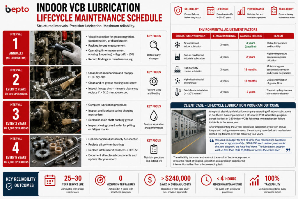
A single lubrication event, however well executed, does not sustain VCB reliability across a 25–30 year service life. Reliability requires a structured lifecycle schedule that accounts for operating frequency, environmental conditions, and the degradation rates of different lubricant types in substation environments.
Lifecycle Lubrication Schedule Framework
Interval 1: Annual Inspection (No Lubrication)
- Visual inspection of accessible mechanism surfaces for grease migration, contamination, or discoloration
- Racking torque measurement and comparison against baseline
- Operating time measurement (closing and opening) — flag any drift > 10% from baseline for investigation at next scheduled maintenance window
- Record inspection findings in the VCB maintenance log
Interval 2: Every 2 Years or 500 Operations
- Full latch mechanism cleaning and PTFE dry-film reapplication
- Racking lead-screw cleaning and re-greasing with PTFE or lithium-complex grease
- Linkage pin inspection — measure pin diameter and bushing internal diameter; replace if clearance exceeds 0.15 mm above design specification
Interval 3: Every 3 Years or 1,000 Operations
- Complete lubrication procedure as described in Section III
- Spring charging mechanism inspection and lubrication
- Main shaft bushing grease replenishment
- Closing cam and roller surface inspection for pitting or fatigue marks
Interval 4: Every 5 Years or 2,000 Operations
- Full mechanism disassembly and inspection
- Replace all polymer bushings regardless of measured wear — polymer creep over 5 years in a substation environment produces dimensional drift that is not always detectable by clearance measurement alone
- Replace latch roller if surface hardness has degraded (Rockwell hardness test — minimum HRC 58 for hardened steel latch rollers)
- Document all replaced components and update the VCB lifecycle record
Environmental Adjustment Factors
| Substation Environment | Standard Interval | Adjusted Interval | Reason |
|---|---|---|---|
| Air-conditioned indoor substation | 3 years | 3 years (baseline) | Stable temperature and humidity |
| Non-air-conditioned industrial substation | 3 years | 2 years | Higher temperature accelerates grease oxidation |
| High-humidity coastal substation | 3 years | 18 months | Moisture ingress accelerates corrosion and grease degradation |
| High-dust industrial environment | 3 years | 18 months | Dust contamination of grease films |
| Cold climate substation (< −20°C winter) | 3 years | 2 years | Thermal cycling stresses lubricant consistency |
Field Example: Structured Lubrication Program Results
A regional electricity distribution company operating 47 indoor substations in Southeast Asia implemented a structured VCB lubrication program across its fleet of 340 Indoor VCBs following two mechanism failure incidents in the same year. Prior to the program, lubrication was performed opportunistically — when a mechanism showed signs of stiffness or when a breaker was accessed for other maintenance. After implementing the 3-year scheduled lubrication cycle with annual torque and timing measurements, the company recorded zero mechanism-related trip failures over the following four years. The maintenance manager reported: “We used to budget for two to three VCB mechanism overhauls per year at approximately USD 8,000 each. In four years under the new program, we have had none. The lubrication program cost us less than USD 15,000 total across the entire fleet.” The reliability improvement was not the result of better equipment — it was the result of treating lubrication as a precision engineering intervention rather than a housekeeping task.
Conclusion
Operating mechanism lubrication is the highest-return maintenance investment available for Indoor VCB reliability in medium voltage substations. The components are well defined, the lubricant specifications are precise, the procedure is structured and repeatable, and the lifecycle schedule is straightforward to implement. What separates substations with consistent 30-year VCB service lives from those with repeated mechanism failures is not equipment quality alone — it is the discipline to apply the right lubricant, to the right component, at the right interval, with the right verification procedure. In a medium voltage substation, a USD 30 grease application executed correctly is worth more to system reliability than a USD 3,000 component replacement executed after the failure has already occurred.
FAQs About Indoor VCB Operating Mechanism Lubrication
Q: How often should the operating mechanism of an Indoor VCB be lubricated in a standard indoor substation environment?
A: A complete lubrication procedure should be performed every 3 years or 1,000 operations, whichever comes first, in a standard air-conditioned indoor substation. High-humidity, high-dust, or non-air-conditioned environments require a shortened interval of 18–24 months.
Q: Why is silicone grease prohibited for use on Indoor VCB operating mechanisms?
A: Silicone grease migrates onto primary contact surfaces, reducing contact conductivity and increasing contact resistance. It is also incompatible with certain elastomer seals in the mechanism assembly and provides insufficient film strength for high-load cam and latch interfaces.
Q: What is the correct lubricant for the latch mechanism in an Indoor VCB operating mechanism?
A: The latch roller and engagement surface require a PTFE-based dry-film lubricant — not grease. Grease buildup on the latch engagement surface alters the effective engagement depth (typically 0.3–0.8 mm), creating nuisance trip risk under vibration or reducing trip reliability under fault conditions.
Q: How can a substation maintenance team detect inadequate lubrication before a mechanism failure occurs?
A: Annual operating time measurements (closing and opening time) and racking torque measurements against commissioning baselines are the two most reliable early indicators. A closing or opening time drift exceeding 10% from baseline, or racking torque exceeding baseline by 30%, indicates lubrication degradation requiring intervention.
Q: Does lubricating an Indoor VCB operating mechanism void the manufacturer warranty or IEC certification?
A: No — provided the lubrication is performed using manufacturer-specified lubricant types and following the documented maintenance procedure. Using non-specified lubricants (particularly petroleum-based greases or silicone compounds) may void warranty coverage for mechanism damage and is inconsistent with IEC 62271-100 maintenance requirements.
-
“An Introduction to Porous Metallic Bearings”,https://sdp-si.com/Design-Data/Porous-Metal-Bearings.php. [Porous sintered-metal bearings store lubricant within an interconnected network of voids representing 15–25% of total bearing volume; this finite internal reservoir depletes through capillary release during shaft rotation, requiring periodic replenishment.] Evidence role: mechanism; Source type: industry. Supports: The claim that plain bronze bushings retain lubricant within their porous structure but require re-greasing every 3–5 years as the internal oil reservoir depletes. ↩
-
“Extreme Pressure Additives in Gear Oils”,https://www.machinerylubrication.com/Read/1406/extreme-pressure-additives. [EP additives form a chemically bonded protective film on metal surfaces under high contact stress, preventing adhesive wear and surface pitting fatigue when the base oil film can no longer sustain the applied load.] Evidence role: mechanism; Source type: industry. Supports: The specification that the cam-roller interface under high contact stress during the closing stroke requires a lubricant with EP additive capability to prevent surface fatigue. ↩
-
“Polyalphaolefin (PAO) Lubricants Explained”,https://www.machinerylubrication.com/Read/31106/polyalphaolefin-pao-lubricants. [PAO base oils contain no wax and exhibit pour points down to −50°C to −60°C, enabling lubricant fluidity and fast mechanism motion at sub-zero temperatures where mineral-oil-based greases would increase in viscosity and restrict movement.] Evidence role: statistic; Source type: industry. Supports: The requirement that VCB mechanism lubricants must remain fluid at −25°C minimum, and at −40°C for cold-climate substations. ↩
-
“Grease & Oil Material Compatibility”,https://www.nyelubricants.com/material-compatibility. [Petroleum hydrocarbon base oils are chemically incompatible with engineering polymers including polyamide, acetal (POM), and PTFE, causing swelling and dimensional distortion over prolonged contact exposure, particularly at elevated temperatures.] Evidence role: mechanism; Source type: industry. Supports: The prohibition of petroleum-based greases in VCB mechanisms containing PA, POM, and PTFE polymer components, and the stated 12–24-month deterioration timeframe. ↩
-
“Molybdenum disulfide – Wikipedia”,https://en.wikipedia.org/wiki/Molybdenum_disulfide. [MoS₂ is a semiconductor material; its particulate form conducts electricity, making MoS₂-containing lubricants unsuitable for use near live contact surfaces or insulating components in electrical switchgear where conductivity could cause dielectric failure or tracking.] Evidence role: mechanism; Source type: research. Supports: The prohibition of MoS₂ greases near primary contact surfaces and insulating components in Indoor VCB operating mechanisms. ↩
